When engineers and manufacturers need to know exactly how a material will behave under stress, they turn to one essential piece of equipment — the Universal Testing Machine (UTM). Whether it involves stretching a steel cable to its breaking point, compressing a concrete block, or bending a plastic sample, a UTM delivers precise, repeatable results that form the backbone of material quality assurance.
Understanding the universal testing machine diagram is the first step toward grasping how this powerful equipment works. By studying the diagram, engineers can identify each component, understand how forces are applied, and trace the path of data from specimen to report. The UTM is not just a machine — it is a complete testing ecosystem.
In this guide, you will explore the full anatomy of a Universal Testing Machine, including its parts, working principle, types of tests it performs, and how to interpret its results. Whether you are a mechanical engineer, a quality control professional, or a student of materials science, this comprehensive resource will sharpen your understanding of material testing.
What is a Universal Testing Machine?
A Universal Testing Machine (UTM) is a mechanical testing equipment designed to evaluate the mechanical properties of materials by applying controlled forces — including tension, compression, bending, and shear — in a single, versatile platform. The term “universal” refers precisely to this ability: one machine capable of conducting multiple types of tests on a wide range of materials.
UTMs are used extensively in manufacturing, construction, aerospace, automotive, and research laboratories to verify that raw materials, finished components, and products meet specified mechanical standards. They generate critical data such as tensile strength, yield strength, elongation, and modulus of elasticity — all of which are essential for product design and safety validation.
From a simple rubber gasket to a high-strength titanium alloy, the UTM provides the objective, quantifiable mechanical data that engineers and quality managers rely on when making critical decisions.
Universal Testing Machine Diagram
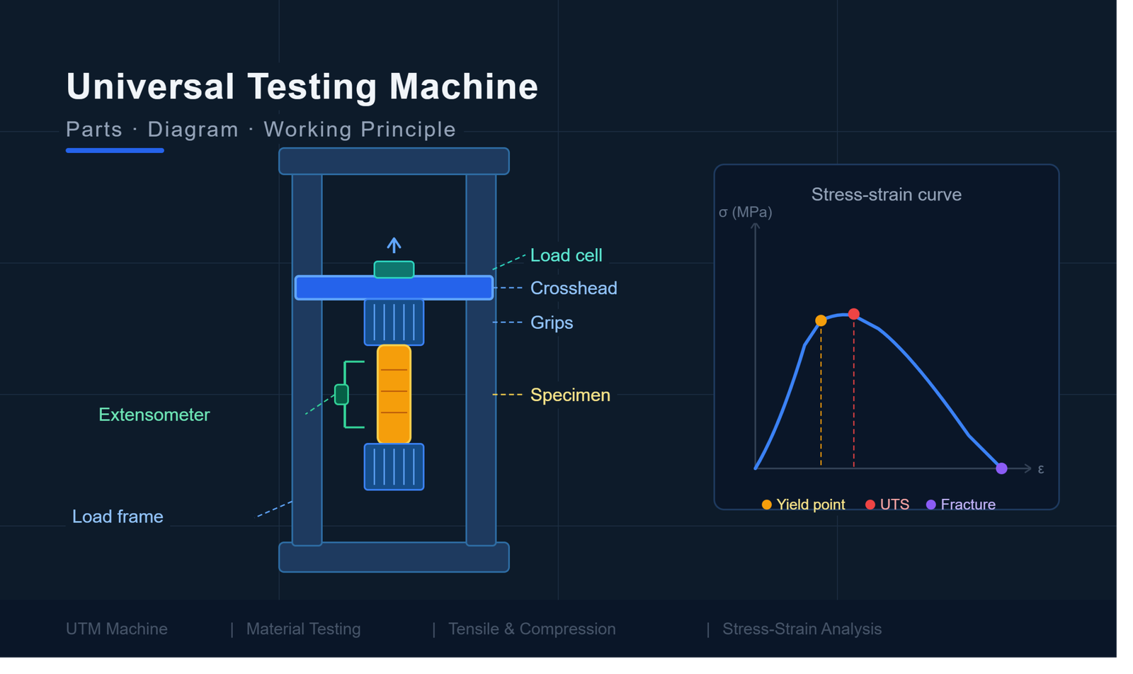
A well-drawn universal testing machine diagram is one of the most useful references an engineer can have. It maps out all the key components in spatial relation to one another, making it easy to understand how the machine operates as a unified system. Typically, the UTM diagram is presented as a labeled cross-section or front-view illustration of the machine, showing both the structural framework and the internal drive mechanisms.
In a standard UTM diagram, you will generally see the following elements clearly labeled:
- Load Frame — The tall, rigid vertical structure that houses all other components.
- Crosshead — The moving horizontal beam that applies force to the specimen.
- Upper and Lower Grips — Fixtures that hold the test specimen securely in place.
- Load Cell — The transducer mounted near the crosshead that measures applied force.
- Extensometer — A precision instrument attached to the specimen to measure deformation.
- Drive System — Hydraulic cylinders or electromechanical screws that move the crosshead.
- Control Panel / Software Interface — The operator control station that manages test parameters.
By studying the universal testing machine diagram, operators can quickly troubleshoot issues, understand force pathways, and identify where each sensor feeds data into the software. The diagram essentially translates complex engineering into a readable visual map.
Parts of a Universal Testing Machine
Each part of a UTM plays a specific, irreplaceable role in ensuring accurate and repeatable material testing. Here is a detailed breakdown of every major component.
1. Load Frame
The load frame is the rigid structural skeleton of the UTM. Typically constructed from high-strength steel columns and a robust base, it provides the mechanical resistance against which force is applied. The load frame must be stiff enough to prevent deflection during testing — any frame flexing would introduce errors into force measurements. UTMs are available in single-column and dual-column frame configurations depending on the load capacity required.
2. Crosshead
The crosshead is the movable horizontal beam within the load frame. It travels up and down along the columns to apply tensile or compressive force to the specimen. The speed of crosshead movement — called the crosshead speed — directly controls the rate of load application, which is a critical test parameter. Crosshead displacement is also used as a secondary measurement of specimen deformation when extensometers are not used.
3. Load Cell
The load cell is the force-measuring transducer of the UTM. It converts mechanical force into an electrical signal that is read and recorded by the system software. Load cells are precision instruments calibrated to specific force ranges, and they must be matched to the expected test loads for accuracy. Using an oversized load cell for a low-force test reduces resolution; using an undersized one risks damage. Modern UTMs often feature interchangeable load cells to accommodate a wide range of test forces.
4. Grips and Fixtures
Grips are the clamping devices that hold the test specimen in place during testing. Different types of grips are used depending on the material and test type — wedge grips for flat tensile specimens, pneumatic grips for delicate materials, and compression platens for compressive tests. The grip design ensures that the applied force is transferred uniformly and axially into the specimen, which is critical for test validity.
5. Extensometer
An extensometer is a precision deformation-measuring instrument that clips onto or contacts the test specimen. While crosshead displacement gives an approximate measure of deformation, the extensometer provides a direct, highly accurate reading of specimen elongation or compression over a defined gauge length. Extensometers are particularly important when precise determination of yield strength and modulus of elasticity is required.
6. Control Panel
The control panel is the operator interface through which test parameters are entered and the test is managed in real time. In older UTMs, this was a panel of analog dials and switches. In modern machines, it is typically integrated with the software interface on a computer or touchscreen, allowing for programmatic test setup, real-time graphing, and automated reporting.
7. Hydraulic or Electromechanical Drive System
The drive system generates and delivers the force applied to the specimen. Hydraulic UTMs use fluid pressure to drive a piston that moves the crosshead — they are ideal for very high-load applications such as structural steel and concrete testing. Electromechanical UTMs use motorized lead screws or ball screws to move the crosshead — they offer superior speed control and are preferred for lower-load precision testing of polymers, composites, and thin materials.
8. Software Interface
Modern UTMs are accompanied by dedicated test software that manages every aspect of the test. The software sets crosshead speed, defines test limits, collects data from the load cell and extensometer, generates stress-strain curves in real time, calculates key mechanical properties, and produces test reports. Leading software platforms offer compliance with standards such as ASTM, ISO, and EN testing protocols.
I am text block. Click edit button to change this text. Lorem ipsum dolor sit amet, consectetur adipiscing elit. Ut elit tellus, luctus nec ullamcorper mattis, pulvinar dapibus leo.
UTM Components at a Glance
| Component | Function | Key Specification |
| Load Frame | Provides structural resistance for force application | Stiffness, load capacity |
| Crosshead | Applies tensile or compressive force to the specimen | Speed range, displacement accuracy |
| Load Cell | Measures applied force as an electrical signal | Capacity, accuracy class (typically 0.5% or better) |
| Grips & Fixtures | Secures the specimen for consistent force transfer | Grip type, jaw face material |
| Extensometer | Measures specimen deformation accurately | Gauge length, resolution |
| Control Panel | Manages test parameters and real-time monitoring | Interface type, programmability |
| Drive System | Generates and delivers force to the crosshead | Hydraulic vs. electromechanical |
| Software Interface | Data collection, analysis, and reporting | Standards compliance, output formats |
Universal Testing Machine Working Principle
The working principle of a Universal Testing Machine is based on the application of a controlled, measurable mechanical force to a test specimen, followed by the precise measurement of the resulting deformation, and the recording of data for analysis. Here is a step-by-step explanation of how a UTM works:
- Sample Preparation: The test specimen is prepared in accordance with the relevant testing standard (such as ASTM E8 for metals tensile testing or ISO 527 for plastics). The specimen is typically machined to a standardized shape and dimensions.
- Specimen Mounting: The prepared specimen is clamped securely into the grips of the UTM. For a tensile test, the specimen is gripped at both ends. For a compression test, the specimen is placed between compression platens.
- Extensometer Attachment: If accurate deformation measurement is needed, an extensometer is clipped onto the gauge length of the specimen at this stage.
- Test Parameter Entry: The operator enters the test parameters into the software — including crosshead speed, data acquisition rate, and any automatic stop conditions (such as specimen failure or a load limit).
- Force Application: The drive system moves the crosshead at the programmed speed. In a tensile test, the crosshead moves upward (or outward), applying a stretching force. In a compression test, the crosshead moves downward, applying a compressive force.
- Data Acquisition: As the crosshead moves, the load cell continuously measures the applied force and transmits the data to the software. The extensometer simultaneously measures the deformation of the specimen.
- Stress-Strain Curve Generation: The software divides force data by the original cross-sectional area of the specimen to calculate stress, and divides deformation data by the original gauge length to calculate strain. This data is plotted in real time as a stress-strain curve.
8.Test Completion: The test automatically stops when the specimen fractures, when a preset load is reached, or at operator command. The crosshead returns to its home position.
- Results Analysis: The software calculates and reports all relevant mechanical properties, including yield strength, ultimate tensile strength, elongation at break, and modulus of elasticity.
Types of Tests Performed Using a UTM
Tensile Test
The tensile test — also called a tension test — is the most commonly performed test on a UTM. The specimen is gripped at both ends and pulled apart until fracture. It determines tensile strength, yield strength, elongation, and reduction in area.
Compression Test
In a compression test, the specimen is placed between platens and a compressive load is applied until the material crushes, deforms, or reaches a specified load. It is widely used for concrete, foam, rubber, and structural components.
Bend Test
A bend test evaluates a material’s ductility and resistance to cracking under bending stress. The specimen is supported at two points and a central load is applied. Common for metals, ceramics, and composites.
Shear Test
Shear testing applies force parallel to the cross-section of the specimen to determine shear strength. It is used for adhesives, bolts, rivets, and laminated materials.
Peel Test
Peel testing measures the adhesive bond strength between two bonded layers by peeling them apart at a controlled angle and speed. It is commonly applied to tapes, laminates, and coatings.
Flexural Test
A flexural test (three-point or four-point bending) measures the bending stiffness and flexural strength of materials such as plastics, composites, wood, and concrete beams.
Tests and Their Industry Applications
| Tensile | Tensile strength, yield strength | Metals, polymers, textiles | Automotive, construction, aerospace |
| Compression | Compressive strength | Concrete, foam, rubber | Civil engineering, packaging |
| Bend | Ductility, crack resistance | Metals, ceramics, composites | Aerospace, manufacturing |
| Shear | Shear strength | Adhesives, bolts, laminates | Structural engineering, electronics |
| Peel | Adhesive bond strength | Tapes, coatings, films | Packaging, electronics, medical devices |
| Flexural | Flexural modulus, strength | Plastics, composites, wood | Construction, consumer goods |
Applications of Universal Testing Machines
Manufacturing
In manufacturing, UTMs are used for incoming raw material inspection, in-process quality control, and finished product testing. They ensure that components meet engineering specifications before assembly or dispatch.
Construction
Construction materials such as steel rebar, concrete samples, cement blocks, and structural timber are routinely tested using UTMs to verify that they meet the mechanical requirements of building codes and structural engineering standards.
Automotive
In the automotive industry, UTMs test everything from seat belt webbing and airbag fabrics to engine components and chassis steel. Material testing ensures vehicle safety and performance standards are consistently maintained.
Aerospace
Aerospace applications demand extremely stringent material performance — UTMs test high-performance alloys, carbon fibre composites, adhesive bonds, and fasteners to meet the exacting standards of aviation and space engineering.
Research Laboratories
Research institutions use UTMs to characterise new materials, develop advanced composites, and validate theoretical material models. The machine is central to materials science research and innovation.
Educational Institutions
Engineering colleges and universities use UTMs in practical laboratories to give students hands-on experience in material testing concepts, allowing them to generate real stress-strain curves and observe material behaviour firsthand.
Advantages of a Universal Testing Machine
- Versatility: A single machine can perform tensile, compression, bending, shear, peel, and flexural tests.
- High Accuracy: Modern UTMs with calibrated load cells achieve force measurement accuracy of 0.5% or better, meeting international standards.
- Wide Load Range: UTMs are available from bench-top models capable of a few Newtons to large floor-standing machines capable of hundreds of kilonewtons.
- Standards Compliance: UTMs are designed to support testing in accordance with ASTM, ISO, EN, and other major testing standards.
- Real-Time Data: Integrated software provides instant stress-strain curve generation and automatic calculation of material properties.
- Reproducibility: Programmable test parameters ensure that every test is conducted identically, yielding consistent and comparable results.
- Wide Material Compatibility: Metals, polymers, composites, textiles, rubber, wood, and biological materials can all be tested with appropriate fixtures.
- Digital Record Keeping: Software interfaces generate detailed test reports that are easily stored, shared, and audited.
How to Read UTM Test Results
Understanding the output of a Universal Testing Machine requires familiarity with several key mechanical parameters:
Stress
Stress (symbol: σ) is the force applied per unit area of the specimen’s cross-section, expressed in Pascals (Pa) or Megapascals (MPa). It is calculated as: Stress = Force / Original Cross-Sectional Area.
Strain
Strain (symbol: ε) is the ratio of the change in length to the original length of the specimen — a dimensionless quantity or expressed as a percentage. It is calculated as: Strain = Change in Length / Original Gauge Length.
Yield Strength
The yield strength is the stress at which the material begins to deform plastically — that is, permanently. It is a critical design parameter for structural components because it marks the boundary between reversible elastic deformation and irreversible permanent deformation.
Ultimate Tensile Strength (UTS)
The Ultimate Tensile Strength (UTS) is the maximum stress that the material can withstand before fracture. It is the highest point on the stress-strain curve and is used to set the maximum allowable working stress in engineering design.
Elongation
Elongation at break (expressed as a percentage) measures how much the specimen stretched before fracturing. It is an indicator of ductility — high elongation values indicate a ductile material, while low values indicate brittleness.
Stress-Strain Curve
The stress-strain curve is the graphical output of a tensile test. It plots stress on the Y-axis against strain on the X-axis and reveals the full mechanical story of a material — from initial elastic behaviour, through yield, plastic deformation, necking, and ultimate fracture. The curve is the most information-rich output of a UTM test.
Factors to Consider When Choosing a UTM
Load Capacity
Select a UTM whose maximum load capacity comfortably exceeds the expected test force for your materials. Choosing a machine with the right capacity ensures both accuracy at the low end and safety at the high end.
Accuracy and Resolution
For precision applications, look for a UTM with high load measurement accuracy (0.5% of reading or better) and high extensometer resolution, particularly when measuring modulus of elasticity.
Test Speed Range
Different materials require different test speeds. Verify that the UTM offers a wide enough crosshead speed range to comply with the testing standards applicable to your materials.
Software Features
Evaluate the software for ease of use, standards compliance (ASTM, ISO), automatic reporting capabilities, data export formats, and the ability to define custom test methods.
Industry and Standards Requirements
Identify which testing standards are mandatory in your industry. Ensure the UTM and its software are pre-validated or certifiable to those standards to avoid compliance issues during audits or product certification.
Conclusion
The Universal Testing Machine is one of the most important and versatile instruments in the world of materials science, quality engineering, and manufacturing. By understanding the universal testing machine diagram — and the individual roles of components like the load cell, crosshead, extensometer, and grips — engineers can unlock the full power of material testing to validate designs, ensure quality, and drive innovation.
Whether you are selecting a UTM for your laboratory, studying for an engineering examination, or working through a material qualification programme, a thorough understanding of UTM parts, working principles, and test types is indispensable. The stress-strain curve generated by this remarkable machine tells a complete mechanical story — from the first elastic deformation to the ultimate fracture — in a single, clean graph.
To explore material testing solutions further, consult with a qualified UTM supplier who can match the right machine, load capacity, and software to your specific application needs and testing standards. Investing in the right Universal Testing Machine is ultimately an investment in the quality and safety of every product you make.
Frequently Asked Questions :
What is a Universal Testing Machine?
A Universal Testing Machine (UTM) is a mechanical testing equipment capable of performing multiple types of force tests, including tensile, compression, bending, shear, and peel tests on a wide variety of materials. It is called "universal" because of its versatility and ability to evaluate different mechanical properties using one machine.
What is the purpose of a universal testing machine diagram?
A universal testing machine diagram provides a labeled visual representation of all major machine components, including the load frame, crosshead, load cell, grips, and extensometer. It helps engineers, students, laboratory personnel, and operators understand the machine's construction, functionality, and testing workflow.
How does a Universal Testing Machine work?
A UTM works by securely holding a test specimen between grips and applying a controlled force through a moving crosshead driven by either a hydraulic or electromechanical system. The load cell measures the applied force, while the extensometer records specimen deformation. Software then generates a stress-strain curve and calculates important material properties.
What are the main parts of a Universal Testing Machine?
The main parts of a Universal Testing Machine include the load frame, crosshead, load cell, grips and fixtures, extensometer, drive system (hydraulic or electromechanical), control panel, and software interface. Each component plays a critical role in ensuring accurate testing and measurement.
What materials can be tested using a UTM?
A UTM can test a broad range of materials, including metals such as steel and aluminium, plastics, polymers, rubber, textiles, fibres, composites, wood, concrete, ceramics, packaging materials, and even biological tissues when appropriate fixtures are used.
What is the difference between tensile and compression testing?
In tensile testing, a specimen is pulled apart to determine its resistance to stretching forces, measuring tensile strength and elongation. In compression testing, the specimen is compressed between platens to evaluate its resistance to crushing forces and determine compressive strength. Both tests can be performed using the same Universal Testing Machine with different fixtures.
Why is a load cell important in a UTM?
The load cell is the primary force-measuring device in a Universal Testing Machine. It accurately records the force applied to the specimen during testing. Without a calibrated load cell, stress calculations and material property measurements would be unreliable, making it one of the most critical components of the UTM.
How accurate is a Universal Testing Machine?
Modern Universal Testing Machines can achieve force measurement accuracy within ±0.5% of the indicated value when properly calibrated according to standards such as ISO 7500-1 and ASTM E4. With high-resolution extensometers, deformation measurements can also achieve excellent precision. Regular calibration is essential for maintaining testing accuracy.